Wednesday, June 15, 2011

New Project: Nixie Clock part 2

The Components

So I had a lot of bad luck building this project.  The fault was my own though.  I made a lot of stupid mistakes like shorting out the driver chips for the Nixie tubes and going though two Arduino mini's before getting a setup that worked. But i'll get into that later.

There were some really cool things about this project that I didn't really realize until I was holding them in my hand. Those things being the Nixie Tubes themselves and their history in the world. The early Nixie displays were made by a small vacuum tube manufacturer called Haydu Brothers Laboratories, and introduced in 1955 by Burroughs Corporation, who purchased Haydu and owned the name Nixie as a trademark. The name Nixie was derived by Burroughs from "NIX I", an abbreviation of "Numeric Indicator eXperimental No. 1." Similar devices that functioned in the same way were patented in the 1930s, and the first mass-produced display tubes were introduced in 1954 by National Union Co. under the brand name Inditron. However, their construction was cruder, their average lifetime was shorter, and they failed to find many applications due to their complex periphery. Nixie tubes were eventually replaced in the 1970s by light-emitting diodes (LEDs) and vacuum fluorescent displays (VFDs), often in the form of seven-segment displays.  


The four tubes I receved from Ogi Lumen were made by the Soviet Union and are stamped CCCP.


They also have date codes printed on them.  All four were made in 1986 in September and November of that year.  I was 5 1/2 years old when they were made.  Its kinda a weird feeling to be holding something that was technically "brand new" in the wrapper and made halfway around the world in a country that technically does not exist anymore.  Thinking of the history that happened while it sat in storage.  I mean, It would be another 5 years before the Soviet Union would collapse, they are older then the Space Shuttle Endeavour, and two of them were made the same time the New York Met last won the World Series.  I don't know, I guess I'm a sucker for history, especially history I lived though.

Another neat part is the controller boards for the tubes that utilize Russian made K155NA1 Driver chips.


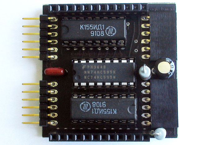
The ones in this picture are newer but two out of my original set were much older and definitely looked as if they were from the 70's or 80's.  Unforgivably, they were both damaged, one permanently due to my negligence.  I shorted one out on a random piece of wire that I had left on my worktable and the other I had flexed the pins too much and two of them broke.  I was able to solder on new pins so it works but it was  a regrettable mistake.  Ohh well, ordered me up some replacements from the fine gentlemen over at Ardunix.

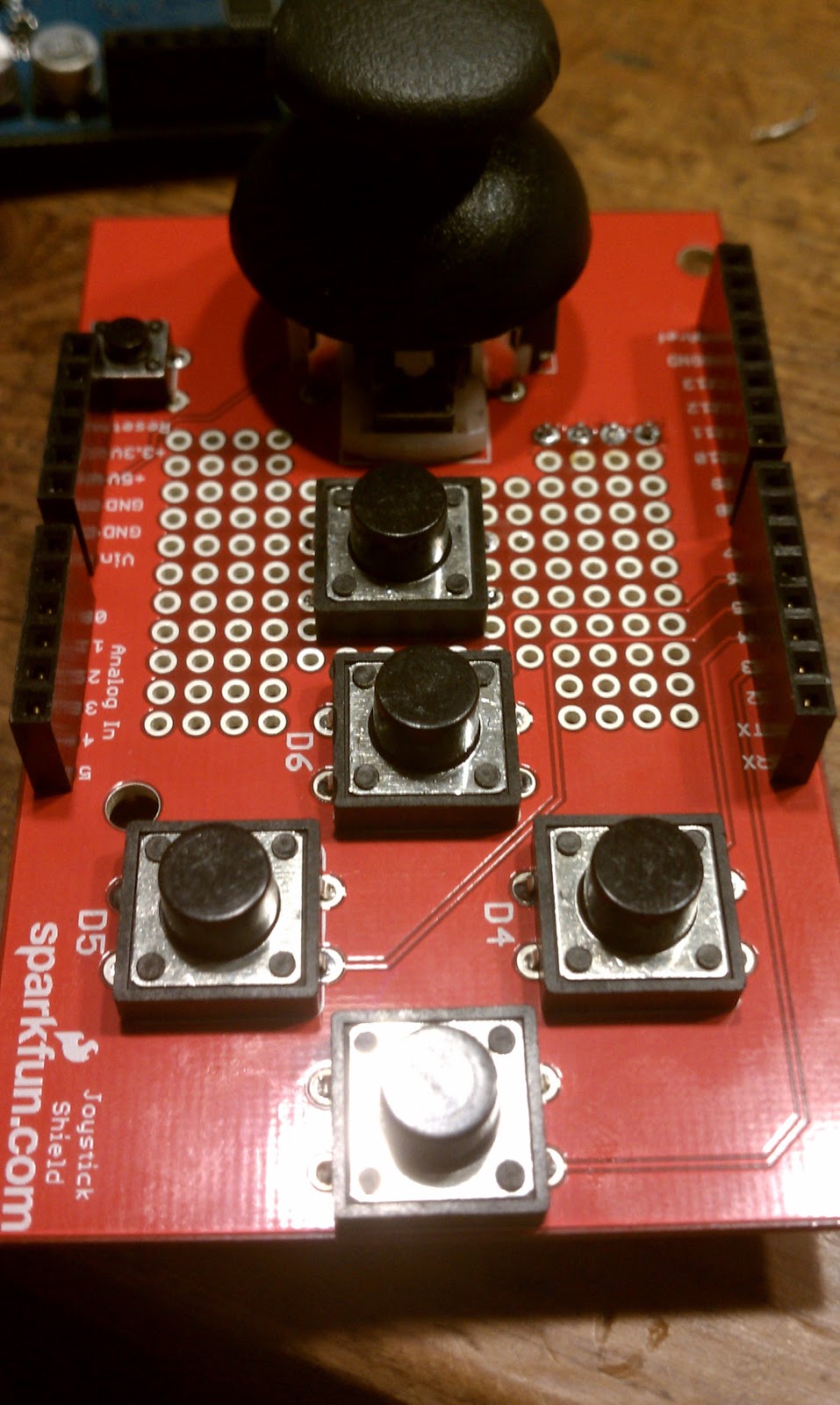
So wiring this project wasn't too big of a deal...in theory.  I had wired up parts of it on my breadboard before I had my Arduino mini but I did run into a few problems with some of the parts I was using.  First don't ever use radio shack perf boards unless you absolutely have to...They are junk!!  I ran into my first issues with soldering the perf boards was that it was very difficult to solder since the solder doesn't stick to the PCB.  But after screwing with my solder points I was able to make a custom sized board for my Arduino Mini that I thought looked really decent.  Unfortunately, due to not really understanding how to regulate the 9v power supply to 5v properly, I over volted my first Arduino board and blew it up.  Crap!  Ohh well, order me up another and away I go.  This time I used a radio shack perf board with copper contacts on them to help with my problem with the solder not sticking to the PCB.  Still, it wasnt the best.  The copper contacts were only on one side and only on the surface which didnt help much.  Plus the contacts weren't evenly spaced really well and caused me to burn up another board when my solder points merged and shorted out the board.    Crap!!!  I did have it going though.  The picture from my last post was using that board, but I tried adding the LED's after I took that picture.  Ohh well, third times a charm, and this time I bought a small 2"x2" perf board from Sparkfun with evenly spaced holes and contacts that passed though the board.  Nice!!!  Here's the finished product:


I cut out one of the mount holes to help make it fit better.  Also I went though a few RGB led's getting them soldered together and fitted behind the tubes.  The first set, I accidentally turned one of the led's around and causing three of them to "blow up".  The second set I tired something different to help my solder them easier but ended up pulling the pins off and was unable to solder them back.  Third times a charm and this time I used a technique used to make RGB LED Cubes.  Wrap in heat shrink tubing and here you go:


So I had mentioned that my first Arduino board smoked due to being over volted.  Well after that I ordered a "breadboard" power supply from sparkfun that will convert 9-12v to 3-5v.  I made a small modification of adding a heat sink to the voltage regulator and painting the super bright red led they had on board with some black model paint I had laying around.  Then I wired it up in parallel with a baral jack plug, which I actually didn't need, as there are pins to solder wires directly to the board but whatever. Then since I had wanted to keep the FTDI cable used to program the Arduino, I grabbed a short usb extension cable from my local pc shop and wired it up so I could use the FTDI cable to power the board.


Here's a short video showing the LED back light running with the clock as my finished product.  


And heres the code I used.  Thanks to the guy over at Tronixstuff for his clock code as well as the guy over at the applied platonics blog for his RGB LED code.  


/*
Nixie tube demonstration code - simple clock
http://tronixstuff.com - John Boxall. February 2011.
Baseon on a sketch originally created by Lionel Haims, July 25, 2008.
Released into the public domain.
*/

#include "Wire.h"
#include "Nixie.h"
#define DS1307_I2C_ADDRESS 0x68

// note the digital pins of the arduino that are connected to the nixie driver
#define dataPin 2 // data line or SER
#define clockPin 3 // clock pin or SCK
#define latchPin 4 // latch pin or RCK

// note the number of digits (nixie tubes) you have (buy more, you need more!)
#define numDigits 4

int narray[numDigits]; // holds the digits to display
int a=0;
// This assumes you're using a RadioShack #276-0028 RGB LED
// 2011-05-12: Note! The anode is the really long pin.
// You'll need to bend it to get it into Digital8.
//
// || || || ||
// || || || ||
// || || || ||
// G B || ||
// || R
// A
// D11 D10 D08 D09

int common_anode = 8;
int red_pin = 9;
int blue_pin = 10;
int green_pin = 11;

int red_min = 150;
int red_max = 255;

int blue_min = 185;
int blue_max = 255;

int green_min = 195;
int green_max = 255;

float h = 0.0;
float s = 1.0;
float v = 0.8;


// Create the Nixie object
// pass in the pin numbers in the correct order
Nixie nixie(dataPin, clockPin, latchPin);

// Convert normal decimal numbers to binary coded decimal
byte decToBcd(byte val)
{
return ( (val/10*16) + (val%10) );
}

// Convert binary coded decimal to normal decimal numbers
byte bcdToDec(byte val)
{
return ( (val/16*10) + (val%16) );
}

void setDateDs1307(byte second, // 0-59
byte minute, // 0-59
byte hour, // 1-23
byte dayOfWeek, // 1-7
byte dayOfMonth, // 1-28/29/30/31
byte month, // 1-12
byte year) // 0-99
{
Wire.beginTransmission(DS1307_I2C_ADDRESS);
Wire.send(0);
Wire.send(decToBcd(second)); // 0 to bit 7 starts the clock
Wire.send(decToBcd(minute));
Wire.send(decToBcd(hour));
Wire.send(decToBcd(dayOfWeek));
Wire.send(decToBcd(dayOfMonth));
Wire.send(decToBcd(month));
Wire.send(decToBcd(year));
Wire.send(0x10); // sends 0x10 (hex) 00010000 (binary) to control register - turns on square wave
Wire.endTransmission();
}

// Gets the date and time from the ds1307
void getDateDs1307(byte *second,
byte *minute,
byte *hour,
byte *dayOfWeek,
byte *dayOfMonth,
byte *month,
byte *year)
{
// Reset the register pointer
Wire.beginTransmission(DS1307_I2C_ADDRESS);
Wire.send(0);
Wire.endTransmission();
Wire.requestFrom(DS1307_I2C_ADDRESS, 7);
// A few of these need masks because certain bits are control bits
*second = bcdToDec(Wire.receive() & 0x7f);
*minute = bcdToDec(Wire.receive());
*hour = bcdToDec(Wire.receive() & 0x3f); // Need to change this if 12 hour am/pm
*dayOfWeek = bcdToDec(Wire.receive());
*dayOfMonth = bcdToDec(Wire.receive());
*month = bcdToDec(Wire.receive());
*year = bcdToDec(Wire.receive());
}

void setup()
{
byte second, minute, hour, dayOfWeek, dayOfMonth, month, year;
pinMode(latchPin, OUTPUT);
pinMode(clockPin, OUTPUT);
pinMode(dataPin, OUTPUT);
Wire.begin();
nixie.clear(numDigits); // clear display
pinMode(common_anode, OUTPUT);
digitalWrite(common_anode, HIGH);

pinMode(red_pin, OUTPUT);
digitalWrite(red_pin, HIGH);

pinMode(green_pin, OUTPUT);
digitalWrite(green_pin, HIGH);

pinMode(blue_pin, OUTPUT);
digitalWrite(blue_pin, HIGH);

Serial.begin(9600);

float h = 0.0;
float s = 1.0;
float v = 0.8;

// Change these values to what you want to set your clock to.
// You probably only want to set your clock once and then remove
// the setDateDs1307 call.

second = 30;
minute = 11;
hour = 17;
dayOfWeek = 3;
dayOfMonth = 11;
month = 5;
year = 11;

//setDateDs1307(second, minute, hour, dayOfWeek, dayOfMonth, month, year);
}

void nixNum(int z)
// displays integer 'z' on 4-digit nixe display
// keeps leading zero, as blank still flickers somewhat
{
narray[0]=int(z/1000); // thousands value
z=z-(narray[0]*1000);
narray[1]=int(z/100); // hundreds value
z=z-(narray[1]*100);
narray[2]=int(z/10); // tens value
narray[3]=z-(narray[2]*10); // ones value
nixie.writeArray( narray, numDigits);
}

void showTime()
{
int zzz=0;
byte second, minute, hour, dayOfWeek, dayOfMonth, month, year;
getDateDs1307(&second, &minute, &hour, &dayOfWeek, &dayOfMonth, &month, &year);
if (bcdToDec(hour)<1) { zzz=minute; } else if (bcdToDec(hour)>=1)
{
zzz=hour*100;
zzz=zzz+minute;
}
nixNum(zzz);
}
void hsv_to_rgb(float h, float s, float v, unsigned char *rc, unsigned char *gc, unsigned char *bc) {
int h_i = ((int)(h/60)) % 6;

float f = (h/60) - (int)(h/60);

float r,g,b;

float p = v * (1.0 - s);
float q = v * (1.0 - f*s);
float t = (1.0 - (1.0 - f)*s);

switch(h_i) {
case 0: r = v; g = t; b = p; break;
case 1: r = q; g = v; b = p; break;
case 2: r = p; g = v; b = t; break;
case 3: r = p; g = q; b = v; break;
case 4: r = t; g = p; b = v; break;
case 5: r = v; g = p; b = q; break;
}

*rc = red_max - (char)((red_max - red_min)*r);
*gc = green_max - (char)((green_max - green_min)*g);
*bc = blue_max - (char)((blue_max - blue_min)*b);
}

//void showDate()
//{
// int zzz=0;
// byte second, minute, hour, dayOfWeek, dayOfMonth, month, year;
// getDateDs1307(&second, &minute, &hour, &dayOfWeek, &dayOfMonth, &month, &year);
// zzz=(dayOfMonth*100)+month;
// nixNum(zzz);
//}

void loop()
{

unsigned char r,g,b;

h += 1;
if (h > 360.0) h -= 360.0;

hsv_to_rgb(h,s,v, &r,&g,&b);
analogWrite(red_pin, r);
analogWrite(green_pin, g);
analogWrite(blue_pin, b);
showTime(); // display the time
delay(100);


//a++;
//if (a==10)
//{
// showDate(); // display the date (day and month) for two seconds
// delay(2000);
// a=1;
//}
}
Even with all the problems I had getting this project finalized I really enjoyed working with this project and looking back at some of the stuff I was doing just a few months ago, I can definitely see a improvement in my abilitys.

I have actually already been asked how much it cost to get this going if i were to make another and I figure it would be about $300 for all the parts.  And now that I know what I'm doing, it probably wouldn't take me much more then a good day to build it.  Also, if you didn't notice, on the first part of these post, I linked a wish list on sparkfun with all the part that I used to make this product with a few more to expand it a little further (add buttons to change the time and turn on/off the back lights) if your interested in building your own. I also work for tips if you like one but don't have the soldering skills to do it yourself.  =D

Hey I've got a wedding to fund!  LOL!

That's it for now.  I think I'm going to take a break for a while while I save up for my wedding so keep it real peeps!

Tuesday, June 7, 2011

New Project: Nixie Clock part 1

And I'm back...

Its been a while since I updated my projects blog.  This is mostly because I got discouraged by my Hard Drive clock project.  I ran into a lot of problems and in the end, I took an extended break from it.  Eventually I may go back to it but for now I have something new and a little easier to work with, Nixie Tubes!!

If you remember from my last post, I was working on a clock project because there is not an easily accessible clock in the house.  Also you may remember that we were on a tight budget last time.  Well I got my excuse to get this project going, I turned 30.  Fitting right?  I thought so.  Also I needed something to break in my new Hakko Soldering Iron I got for my birthday.  Its awesome btw.  0-400 degrees in 10seconds.  Beats this shit out of the one I have at work.  I can go out for coffee before that one gets warm enough to melt solder.

So what are Nixie Tubes again?  A Nixie tube is an electronic device for displaying numerals or other information. The glass tube contains a wire-mesh anode and multiple cathodes. In most tubes, the cathodes are shaped like numerals. Applying power to one cathode surrounds it with an orange glow discharge. The tube is filled with a gas at low pressure, usually mostly neon. Nixies were used as numeric displays in early digital voltmeters, multimeters, frequency counters and many other types of technical equipment. They also appeared in costly digital time displays used in research and military establishments. They have been made obsolete by LED technology.

Except for in the Soviet Union, where they were mass produced into the '90s.

OK!  So lets get the parts list going cause a lots changed in the last few months.

Parts!

For this project, I ordered my Nixie Tubes from http://www.ogilumen.com.  Their kit was very easy to use and there were great instructions on their website for putting the parts together.  Here is what I ordered:

50 mA NIXIE TUBE POWER SUPPLY
OGI LUMEN provides this heavy lifter high voltage switch mode power supply pre-assembled.

It is currently offered in a 50mA output version, adjustable from 150 to 220 VDC, from a 9 to 16 VDC source. There is sufficient power produced by one 50 mA NIXIE TUBE POWER SUPPLY to drive twelve NIXIE DUO boards (twenty-four IN-12A nixie tubes). Our 12 VOLT AC/DC ADAPTER will easily drive this nixie tube supply.


NIXIE DUO and NIXIE DRIVER KITs
All parts provided for solder assembly of pictured extra thick epoxy boards. You get two phenolic sockets, two shiny NOS IN-12A nixie tubes, and all the other bits you'll need. The NIXIE DRIVER prepares a NIXIE DUO to receive serial input from an external microcontroller (Arduino), and power from a NIXIE TUBE POWER SUPPLY. You can further string these assemblies end-to-end for rows of humming digits.NIXIE DUO and NIXIE DRIVER KITs
I ordered 2 of the Nixie Duo and Nixie Driver Kits since I needed 4 digits. 

The next set is from http://www.sparkfun.com.  I ended up needing a lot of little parts so for simplicity, i created a wish list which you can access here:  Parts for Nixie Tube Clock  I'll try to explain what the "odd" parts are for quickly:

Momentary Push Button Switch: Controls to change time as well as "theme"

Triple Output LED RGB: Back light for the Nixie Tubes

FTDI Cable 5V: Programming cable for my Arduino mini Pro

Breadboard Power Supply 5V/3.3V: Ran into problems my first build getting steady 5v power to my Arduino. I ended up burning out the boot loader on my first Arduino as well as two voltage regulators, so I got this for simplicity. There are heat sinks in the list for the voltage regulator as well.

DC Barrel Jack Adapter: Got this to easily connect the Breadboard Power Supply in parallel to my Nixie Tube Power Supply.

Screw Terminals 5mm Pitch (2-Pin) & (3-Pin): Got these to easily connect my lines to the Nixie Tube Power Supply without jacking up the solder points.  I added these to the list in retrospect since I ended up soldering and desoldering my power lines a few times and damaging the board a little.

I also picked up a small 9"x20" Shadow Box from Michael's to house the project.  I had to modify it a little for my purposes.  I removed the glass panel because the box ended up being not deep enough and I replaced the foam board backing with a 3/8" thick piece of basswood from JoAnn Fabrics as well as some black fabric from JoAnn as well.  I used two layers of the fabric hide the cables I ran underneath.  Finally, I went to radio shack and picked up a sheet of perforated board for any small custom sized boards i need as well as a pack of 100ohm resistors for the led back lights.

The Build
So here is the working project.  I'll post how I built the clock later.  For now, Enjoy.

Monday, March 21, 2011

New Project: HD Clock - Intro

So this week, I got DirecTV installed and I finally got rid of Comcast.  Were i live, the Comcast service is a joke and I'm paying a lot for their HD service that doesn't include much.  DirecTV on the other hand gives me a ton of HD and for the first year, I'm saving like $20 a month on my bill which includes all the movie channels.  Just in time for "Game of Thrones" Next month on HBO! (OMG!!!)  Well, one of the downsides is that my girl and I had really got used to seeing the time displayed on our Comcast receivers and the new DirecTV ones don't display the time, which ended up being very annoying.  The only other clocks in the house are our phones, our computers, or the clock on the stove in the kitchen.  This got me thinking as to what i could do with my Arduino to display the time.  My first though was, "Hell yes, a reason to do the Nixie Clock!" but my Girl told me i was on a tight budget for this project and i was all <sadface>.

So I've got $20 ish to spend on making each clock I need so I headed on over to Sparkfun.com.  Originally I planned on taking a look at LED matrix's to see what i could do with that.

My first though was to use a LOLshield since the led's were individually addressable and it fits right over a Arduino.  But as I was looking around sparkfun, i found these guys:

                                
They are a led matrix built into one common cathode housing that I think look awesome.  The tricolor one was bigger and a lot more expensive then the red and green version so as much as i'd like to get the tricolor it was out of my price range.  So i started looking up code for a LED clock.  In my search, i found this:


Its a Pong Clock using a version of the Arduino with the Real Time clock chip built in.  Each side looses on purpose as the time changes.  Hell yes!  A clock and a nod to my gamer roots, what more could you want?  So i dug up a version of the instructions and was dismayed to see how much I needed to get.  Because there were so many LED's to activate, i needed either a larger micro controller like the Arduino Mega or a bunch of stuff that was going to raise the roof on the price well outside my budget.  Poop.  So i dug around some more and was intreged to find these little gems.


The one of the left, the creator calls a Strobeshnik Digital Clock and it involves etching out numbers on a hard drive platter and spinning the disk so fast that the blinking led's underneath only turn on when the right number is over top them.  This happens faster that the human eye cant perceive and you see the correct time. That sounded awesome but the engraving part was something out of my area of expertise (note: my boss, Van, does metal engraving.  See what he might be able to do.).  The one on the right however uses a RGB led strip around the outside of the disc area and a notch, dremeled out of the platter which, because of the same high frequency blinking leds, show an Analog style clock with Hour, Minuit, and Second hands.  Now that sounded like something i could do and on the cheap since i have a huge stack of old dead drives at work.  Plus the parts required were dirt compared to everything else i saw.  I got enough parts to make three of these guys for $30, minus the Arduino controllers (forgot them this order), and two day shipping.  Right in budget!  Find a quiet enough drive in my stack and huzzah! heres our new clock.  Im going to be following the instructions from this Instructables documentation and documenting my success's and failures.  Once i get things the way I like, I plan on getting a few Arduino Mini Pro's  and work on packaging up this guy real nice like.  Thats it for now, I'll post again once i get the parts I need and can start working on this guy.  Later! 

Thursday, March 10, 2011

The Bluetooth Joystick Project Part 2

Its finally done! It needs a few tweaks here and there to clean it up some but for all purposes, its good to go.  This post is going to be long winded and light on the pictures, but I'm going to try to convey what I've learned over the last few days.


Ok quick recap! When we last left off, I needed to look into the software side of interfacing between my Arduino and my Android Phone.  I needed to be able to assign keys in the SNES Emulator app, SNesoid, it looked like I needed to emulate a hardware keyboard. Theres an option for Bluetooth controllers in the app, but unfortunately its for devices that are identified as an input devices like keyboards. All I had was the modem so I needed to work around that.

After some digging around and finding some guys that had tried something similar but with actual Nintendo controllers, I had come up with a basic idea of what i needed to do. First, I had to get and install the Amarino Toolkit on my android phone. What Amarino does basically is receive data over the Bluetooth connection from my Arduino and present it to my Android phone as data it can use. Second I needed to take that data and use it to act like button presses on a keyboard. For this, I needed a keyboard app on my phone to take the data I was sending, read it, and press a button depending on what data it saw. Luckily for me a lot of this was already done and I just needed to modify it for my application.

The following files are needed before we continue if your following along.  Get them from the Amarino Toolkit website.
Amarino - Android Application
Amarino Plug-in Bundle 
MeetAndroid - Arduino Library

The Arduino side
Ok so I said I had found some guys that had already done a similar project using actual controllers.  This Forum Post and this guy's code basically explains the output from the NES controller.  How a NES controller communicates is by sending 8 bits of data (1 byte) to the console every button press and refreshing the information via a "heartbeat" timer every 16 milliseconds.  Each bit relates to a button press on a NES Contoler as there were only 8 buttons.  Up, Down, Left, Right, A, B, Start, and Select.   That data was sent in a string and looked like the following:
01111111 = A
10111111 = B
11011111 = Select
11101111 = Start
11110111 = Up
11111011 = Down
11111101 = Left
11111110 = Right
Notice the "0", thats the bit being turned off to represent the button press. Alright now I have the format of the data I needed but the code in that forum post was no good to me because it relied on the controller to send the data already formatted and timed.  I didn't have that so my Arduino would need to take care of that on its own.  My Next problem was that I needed a SNES controller instead of the NES.  Luckily, Nintendo didn't stray too far from the tree in that regard.  Easier to do what you know right?  The SNES controller was designed off the original NES but since it had four more buttons, the original 8 bit data couldnt handle it, so they bumped it to 16 bit.

01111111 11111111 - B
10111111 11111111 - Y
11011111 11111111 - Select
11101111 11111111 - Start
11110111 11111111 - Up
11111011 11111111 - Down
11111101 11111111 - Left
11111110 11111111 - Right
11111111 01111111 - A
11111111 10111111 - X
11111111 11011111 - L
11111111 11101111 - R

Notice that there are four more bits that can be used, that never were on the official controller.  I think they might have been left there for expansion, or for third party developers.  But in reality, its more likely that its just cheaper and easier to do the 16 bit processing that computer devices were already being designed around instead of developing a whole system around 12 bit processing.  Not to say it cant be done, but why not use what already being mass produced for the commercial market and save yourself the money. Plus it allowed for expansion and third party developers that you could make money off of without having to reinvent the wheel.  Those four bits would come in handy for me as I ended up needing them for diagonal directions.

The next part was coding the Arduino.  In my initial tests with the NES config, i was able to send char data and covert it to binary in the send command.  But once i had two bytes of data, i couldn't do the conversion anymore.  The way the meetAndroid library works it seems, is that for every send, its one line, and i needed to put two strings of data in one output.  Or at least, thats what I thought.  Then I realized, it didn't matter how I sent it, it was going to only be string data anyway because thats how the meetAndroid Library sends data.  So I cut out the middle man and put my string in a variable, then sent the variable.  This is what i came up with:

Note: dont load this code just yet...we still need to make one more change.

// Load the meetandroid Library
#include <MeetAndroid.h>
MeetAndroid meetAndroid;

// Store the Arduino pin associated with each input
// Select button is triggered when joystick is pressed

int PIN_BUTTON_SELECT = 2;
int PIN_BUTTON_START = 7;
int PIN_BUTTON_A = 3;
int PIN_BUTTON_X = 4;
int PIN_BUTTON_B = 5;
int PIN_BUTTON_Y = 6;
int PIN_ANALOG_X = 0;
int PIN_ANALOG_Y = 1;

// creat intergers to store the state of each button press
int VAL_SELECT;
int VAL_START;
int VAL_A;
int VAL_X;
int VAL_B;
int VAL_Y;
int VAL_updown;
int VAL_leftright;

void setup() {
  //start serial communications at 9600 baud rate
  Serial.begin(9600);

  // Initiate which pin is being read and internal pull-ups for that pin

  pinMode(PIN_BUTTON_A, INPUT);
  digitalWrite(PIN_BUTTON_A, HIGH);

  pinMode(PIN_BUTTON_Y, INPUT);
  digitalWrite(PIN_BUTTON_Y, HIGH);

  pinMode(PIN_BUTTON_X, INPUT);
  digitalWrite(PIN_BUTTON_X, HIGH);

  pinMode(PIN_BUTTON_B, INPUT);
  digitalWrite(PIN_BUTTON_B, HIGH);

  pinMode(PIN_BUTTON_SELECT, INPUT);
  digitalWrite(PIN_BUTTON_SELECT, HIGH);

  pinMode(PIN_BUTTON_START, INPUT);
  digitalWrite(PIN_BUTTON_START, HIGH);
}
// SNES Button Reference
// 01111111 11111111 - B
// 10111111 11111111 - Y
// 11011111 11111111 - Select
// 11101111 11111111 - Start
// 11110111 11111111 - Up
// 11111011 11111111 - Down
// 11111101 11111111 - Left
// 11111110 11111111 - Right
// 11111111 01111111 - A
// 11111111 10111111 - X
// 11111111 11011111 - L
// 11111111 11101111 - R
// My additions to it for this project
// 11111111 11110111 - Up Left
// 11111111 11111011 - UP Right
// 11111111 11111101 - Down Left
// 11111111 11111110 - Down Right

// NES Button Reference:
// UP = 11110111
// DOWN=11111011
// LEFT=11111101
// RIGHT=11111110
// SELECT=11011111
// START=11101111
// A=01111111
// B=10111111

void loop() {

  // reads the current value of each digital pin

  VAL_SELECT = digitalRead(PIN_BUTTON_SELECT);
  VAL_START = digitalRead(PIN_BUTTON_START);
  VAL_A = digitalRead(PIN_BUTTON_A);
  VAL_B = digitalRead(PIN_BUTTON_B);
  VAL_leftright = analogRead(PIN_ANALOG_X);
  VAL_updown = analogRead(PIN_ANALOG_Y);
  VAL_X = digitalRead(PIN_BUTTON_X);
  VAL_Y = digitalRead(PIN_BUTTON_Y);

  // start of the if/elseif/else chain to determin if the button is pressed and to send the string data to the Android Phone

    if (VAL_SELECT == LOW)
    {
      char controller_select[] = "11101111111111111";
      meetAndroid.send(controller_select);
    }
    else if (VAL_START == LOW)
    {
      char controller_start[] = "11110111111111111";
      meetAndroid.send(controller_start);
    }
    
    else if (VAL_A == LOW)
    {
      char controller_a[] = "11111111101111111";
      meetAndroid.send(controller_a);
    }
  
    else if (VAL_B == LOW)
    {
      char controller_b[] = "10111111111111111";
      meetAndroid.send(controller_b);
    }
    else if (VAL_X == LOW)
    {
      char controller_x[] = "11111111110111111";
      meetAndroid.send(controller_x);
    }
    else if (VAL_Y == LOW)
    {
      char controller_y[] = "11011111111111111";
      meetAndroid.send(controller_y);
    }
  
    // this part checks joystick position and sends the string data based on if conditions are met
    
    else if (VAL_leftright < 256 && VAL_updown > 256  && VAL_updown < 768)
    {
      char controller_left[] = "11111110111111111";
      meetAndroid.send(controller_left);
    }
  
    else if (VAL_leftright > 728 && VAL_updown > 256 && VAL_updown < 768)
    {
      char controller_right[] = "11111111011111111";
      meetAndroid.send(controller_right);
    }

    else if (VAL_updown > 768 && VAL_leftright > 256 && VAL_leftright <768)
    {
      char controller_up[] = "11111011111111111";                                                                                                                                
       meetAndroid.send(controller_up);}
  
    else if (VAL_updown < 256 && VAL_leftright > 256 && VAL_leftright < 768)
    {
      char controller_down[] = "11111101111111111";
      meetAndroid.send(controller_down);
    }

    else if (VAL_leftright < 256 && VAL_updown > 768)
    {
      char controller_upleft[] = "1111111111110111";
      meetAndroid.send(controller_upleft);
    }

    else if (VAL_leftright > 768 && VAL_updown > 768)
    {
      char controller_upright[] = "1111111111111011";
      meetAndroid.send(controller_upright);
    }

    else if (VAL_leftright < 256 && VAL_updown < 256)
    {
      char controller_downleft[] = "1111111111111101";
      meetAndroid.send(controller_downleft);
    }

    else if (VAL_leftright > 768 && VAL_updown < 256)
    {
      char controller_downright[] = "1111111111111110";
      meetAndroid.send(controller_downright);
    }
  
    // Final string data to be sent.  this says no buttons were pressed, do nothing.
  
    else  {
      char controller_null[] = "11111111111111111";
      meetAndroid.send(controller_null);
          }
  
  }
  
If you notice, theres actually 17 bits of data.  This is because when expanding the Keyboard app code to except 16 different if else statements from the original 8, something went wrong and my string being sent for the letter "B" wasn't being accepted.  I'm still not 100% sure why but I'm terribad at Java coding and don't understand the code very well.  It works, thats all i'm saying.  This code also doesn't have the Left and Right Shoulder buttons but using the data from the reference, it can be added with ease.  Its already been setup in the keyboard app for the phone.

The last part I needed to do is change the baud rate on the Bluetooth to match my code.  I had to slow it down to 9600 for two reasons.  1) the meetAndroid/Amarino app doesn't work well if you have you baud rate higher then 57600 and 2) the Arduino Uno SMD i was using apparently has a small issue that I was having intermittently running at 57600.  So I just dropped it to 9600 since its a good safe speed.  To change the baud rate on the Bluesmirf Bluetooth modem, you have to terminal into it.  For this I just used the BlueTerm app on my phone i used earlier.  Then i followed the following steps then loaded the sketch into my Arduino.  Again, when uploading to the Arduino, don't connect the Bluetooth to the TX/RX pins.  It wont work.

-Power up BlueSmirf
-Make connection through your Terminal and get the green led
-Type "$$$" before 60 secs from the power up, and it should respond with "CMD" and the red LED will flash
-Type "H" -> list of commands
-Type "SU,9600" -> to change the baudrate and respond "AOK"
-Type "D" -> Display settings to see the new baudrate.
-Reboot the BlueSmirf to make the change happen.
The Android side
Im not going to get long winded about the Android side because, to be honest, there's a lot I do not understand.  Makes me really wish i would have tried harder when I was learning Java programing all those years ago.  Ok so at this point, I installed the Amarino app and plugin bundle on my phone.  You probably don't need the bundle but its got some neat stuff you can output with if you want to play later.

Now, this is where my knowledge got fuzzy.  I wont copy/paste the code here because theres a lot of it and it  would go on forever.  But i will say that if you want to follow along, you'll need the Android SDK and Eclipse for the next part.  The Android SDK is the developer tools for writing Android apps and Eclipse is the Java code writing app that the SDK has been linked up with.  Both are free and opensource, which is awesome.  Heres the modified Software keyboard for you to download that I modified from this guys.  To open this project, unzip the file and import the existing project into the eclipse workspace.  Then find the softkeyboard.java under the src folder.  This is where all the programing takes place.  The only thing i did, was expand the existing commands at the bottom from reading 8 different strings to 16 (nes to snes) and add the variables for the SNES buttons.  Also, and this is important if you want to use the app for your own.  You will need to change the following line to match your Bluetooth's mac address:
private static final String DEVICE_ADDRESS =  "00:06:66:42:07:DD";
This line is near the top of the code and should be easy to find.  If you look toward the bottom, you'll also see how the code checks for where the "0" is in the string being sent, i think.  I seriously had no idea what was really going on but it worked. I tried to just expand on what was there by following the original code and expanding the If/Else statements but I did have a problem with the first one and thats why I added the 17th bit on the Arduino side.  It works, thats all I'm saying.  Maybe one day i'll clean it up when I learn more about Android programing but for now, it will have to do.  Once you made your Mac Address changes, export the program as a Android Application which will provide you with an APK file that you can copy to your phone's sdcard and instill.

Now to get the code to work, you'll have to follow the following steps.  First, fire up Amarino and connect it to you Bluetooth.  If everything working, you can launch the monitor and watch the commands being sent.  Second, install the softkeyboard app and select it as an input method under your phones settings > language & keyboard settings.  This gives you the option to switch your input method.  Third, fire up a text editor like ColorNote, or even just a text message and hold your finder down on the text input area.  A popup will show asking if you want to change your text input method. Change it to Sample Soft Keyboard and watch the top bar on you phone for the device to connect.  Once thats done, you can can test the joystick by hitting the buttons and moving the joystick.  If its worked up to this point, you'll start seeing text and numbers being typed out.  Lastly, fire up SNesoid, and bind the buttons to the programs Input settings.  You can now play Legend of Zelda!  Huzzah!

Bugs and other stuff
So not everything is perfect, and this still needs work but it is playable.  Not bad for a few days work going in blind. The biggest play issue I have right now is that the Joystick needs to be re-centered in order to move in different directions sometimes.  I'm not really sure where thats coming from.  It could be my baud rate, or my Arduino code, the code in my Keyboard, or even be the emulator.  It looks good and smooth reading the data in the Amarino monitor but who knows.  At this point though, I'm happy with what I've accomplished enough to put it down for a while until I learn some more about Arduino and Android programing.

The controller is still not 100% complete though.  I need to get it in a housing to protect it while its in my back pocket as well as make it a little smaller.  My idea of powering the joystick off the phone looks like it wont work but there are lithium ion battery packs that can be had and attached to a shield that easily attaches to the bottom of the joystick and can be charged over usb when needed.  Also, theres versions of the Arduino like the Mini Pro thats the same size as the Bluetooth modem used in this kit, that can help shrink the footprint.  I may end up doing that one day.  Finally, theres the shoulder buttons.  There are plenty of digital pins left that can be used easily.  Just get a right angle header or two and attach two buttons to breakout boards, add the code to the Arduino sketch and your good to go.  I've actually already programed the data into the softkeyboard app so its ready for the info.  Well thats It for now, if you were trying to follow along and need help, leave me a message and i'll try to get back to you, otherwise, see you next project!

Saturday, March 5, 2011

The Bluetooth Joystick Project Part 1

Huzzah!  I got my parts from sparkfun.com in the mail yesterday!  Weekend project, here we go!  For reference, the design of this project is to make a Bluetooth game pad to play The Legend of Zelda on my Android phone's SNES Emulator.


I started a few days ago planning out the details of my project.  Theres a lot that I don't know so its a total learning experience.  One thing i didn't consider before buying the parts was how i was going to connect everything up, theres only so many input pins.  So I put this together in paint to get a visual:


Ahh, good old mspaint.  Things look good and theres plenty of extra pins, no worries. 

If you can tell, theres a 5th Push Button Switch, identical from the others that wasn't in my original parts list.  This is because i totally forgot about the start and select buttons.  The joystick has a pushbutton built in that i'll use for select but i needed a separate start button.  Also, you may be wondering, if you are knowledgeable about SNES controllers, that theres no left or right shoulder buttons.  For now, i left them out but i do have room to put them in later. The original scope of the project though was to build a controller to play Legend of Zelda which happens to not utilize the Left or Right shoulder buttons.  Also, i'd need to find or make my own PCB in order to to place them in a spot that can be utilized as originally intended.  As for putting all the parts together for the Joystick, Sparkfun.com has a great tutorial on building the Joystick here.  I'm going to divert to this tutorial for this part of the project, they can explain thing and show them off better then I can anyway.

The next problem is where Im going to place the Bluetooth card in all this.  With luck the card is actually very small.  I guess i just didn't conceptualize it right but what i ended up doing was soldering it to the underside of the joystick PCB.  Like so:


Excuse my soldering job, I'm still learning.  As you can see in the pictures, i used some breakaway headers and attached it to the prototyping area.  Theres plenty of room, so much so that i was able to run lines around and under the Bluetooth modem.  Also as a note, the joystick board doesn't sit all the way down on my Arduino's headers due to the usb port, so i used that to my advantage while wiring.

Once i got the hardware all connected, i need to get configuation data from the joystick.  Sparkfun.com has an amazing tutorial to get started with their joystick here.  Again, i'm going to divert to their tutorial over explaining things here, its better then anything I work up as an amateur. 

The next part is getting the Bluetooth to connect to my phone.  For this project, I've found an app on the android market called BlueTerm by pymasde.es.  Its free and open source, which is awesome.  What we are going to do here is take what we've learned from Joystick tutorial and instead of outputting the data over the usb connection, we are going to forward it over the Bluetooth connection and see if the BlueTerm app will pick it up.  The great thing though is, we wont have to modify the code at all to get this to work.  The way I wired the Bluetooth modem is via the TX and RX pins on the Arduino board which should send everything we are doing to the modem.  One catch, you cant have the Bluetooth modem connected to the TX/RX pins while uploading, it wont work. I slightly modified their final code to add my new button and adjust the output:  
// Store the Arduino pin associated with each input
// Select button is triggered when joystick is pressed

const byte PIN_BUTTON_SELECT = 2;
const byte PIN_BUTTON_START = 7;
const byte PIN_BUTTON_RIGHT = 3;
const byte PIN_BUTTON_UP = 4;
const byte PIN_BUTTON_DOWN = 5;
const byte PIN_BUTTON_LEFT = 6;

const byte PIN_ANALOG_X = 0;
const byte PIN_ANALOG_Y = 1;


void setup() {

// Start the Serial connection

  Serial.begin(115200);

// Read the input from the digital pin (1 and 0)

  pinMode(PIN_BUTTON_RIGHT, INPUT);
  digitalWrite(PIN_BUTTON_RIGHT, HIGH);
  pinMode(PIN_BUTTON_LEFT, INPUT);
  digitalWrite(PIN_BUTTON_LEFT, HIGH);
  pinMode(PIN_BUTTON_UP, INPUT);
  digitalWrite(PIN_BUTTON_UP, HIGH);
  pinMode(PIN_BUTTON_DOWN, INPUT);
  digitalWrite(PIN_BUTTON_DOWN, HIGH);
  pinMode(PIN_BUTTON_SELECT, INPUT);
  digitalWrite(PIN_BUTTON_SELECT, HIGH);
  pinMode(PIN_BUTTON_START, INPUT);
  digitalWrite(PIN_BUTTON_START, HIGH);
}
// start the loop reading the pin data and printing that data over the serial conncetion

void loop()
{
  Serial.print("left:");
  Serial.print(digitalRead(PIN_BUTTON_LEFT));
  Serial.print(" ");

  Serial.print("right:");
  Serial.print(digitalRead(PIN_BUTTON_RIGHT));
  Serial.print(" ");

  Serial.print("up:");
  Serial.print(digitalRead(PIN_BUTTON_UP));
  Serial.print(" ");

  Serial.print("down:");
  Serial.print(digitalRead(PIN_BUTTON_DOWN));
  Serial.print(" ");

  Serial.print("x:");
  Serial.print(analogRead(PIN_ANALOG_X));
  Serial.print(" ");

  Serial.print("y:");
  Serial.print(analogRead(PIN_ANALOG_Y));
  Serial.print(" ");

  Serial.print("select:");
  Serial.print(digitalRead(PIN_BUTTON_SELECT));
  Serial.print(" ");

  Serial.print("start:");
  Serial.print(digitalRead(PIN_BUTTON_START));
  Serial.print(" ");

  Serial.println();
  delay(500);

}
 
First thing I did was pair the device like normal under the phones Bluetooth settings.  The pass code for the Bluetooth modem is default "1234".  I Then fired up BlueTerm and connected to the Bluetooth modem:


Immediately I got the serial output just like i should which was very exciting.  I tested the range and i was getting signal from a lot further then i'd ever need it to be, even if i had it output to a TV.  


The last image shows me pressing one of the buttons while moving the joystick.  The delay in the code is set to half a second but if i pulled it out, you'd see x,y coordinates move more fluidly.  The next problem is getting the phone to take the input its receiving and act like its key presses on a keyboard.  This is where i hit a wall and where im going to have to come back.  Its looking like i may need to write my own, or "borrow" a software keyboard app that accepts the inputs and tags them to a alphanumeric key.  Luckily, Google has a example software keyboard in their Android SDK that I'm going to take a look at and see how it works.  Another lucky break is that theres a guy that wrote a toolkit called Amarino that makes it easier to interface my Arduino to my Android.  Hopefully it will be some help in this regard.  Now i need to go read up on everything.  Later!

Tuesday, March 1, 2011

Concepts for upcoming projects

Ok so I've come up with a few new ideas for projects I'd like to play with.

The Bluetooth Joystick Project
Concept and scope of use:
To create a handheld, usb powered game pad using the joystick kit from sparkfun.com with a Bluetooth modem in order to connect to my Droid Incredible Smartphone to play The Legend of Zelda on my phone's SNES emulator.  
Parts:
Both of the following items have already been purchased from Sparkfun Electronics.

Joystick Shield Kit
sku: DEV-09760
Description: The Joystick Shield kit contains all the parts you need to enable your Arduino with a joystick! The shield sits on top of your Arduino and turns it into a simple controller. Five momentary push buttons (4+ joystick select button) and a two-axis thumb joystick gives your Arduino functionality on the level of old Nintendo controllers


Bluetooth Modem - BlueSMiRF Silver

sku: WRL-10269
Description: The BlueSMiRF Silver is the latest Bluetoothwireless serial cable replacement from SparkFun Electronics! This version of the popular BlueSMiRF uses the RN-42 module which has a bit less range than the RN-41 module used in the BlueSMiRF Gold. These modems work as a serial (RX/TX) pipe. Any serial stream from 9600 to 115200bps can be passed seamlessly from your computer to your target.


Notes:
The basic problem is that the SNES emulator works great but my big thumbs cover most of the touchscreen and its difficult to use the on screen controls.  The idea for this project being, if can use my Ardunio to take the input from my joystick and buttons and then output those commands over bluetooth in a way that my SNES emulator will use them.  We will see how it all turns out when i get my parts in the next week.

Bonus points:  If the concept works, repackage it and see if its viable to use the phones battery over usb to power the joystick.

The Speedometer Project
Concept and scope of use:
To create a Digital Speedometer with a Odometer and Compass functions.
Parts:

Serial Miniature LCD Module 1.44"

sku: LCD-10090
Description: The uLCD-144(GFX) is a compact and cost effective  display module using the latest state of the art LCD (TFT) technology with an embedded GOLDELOX-GFX2 graphics processor that delivers ‘stand-alone’ functionality to any project. Powerful graphics, text, image, animation and countless more features are built inside the GOLDELOX-GFX2 chip.


Im actually buying this as individual parts instead of a kit.  

GPS Shield

sku: GPS-10102
Description: Adding GPS to your Arduino has never been easier. The multiple GPS receivers attach easily to the shield, and with the example sketch, you will be able to locate your exact position within a few meters.

20 Channel EM-406A SiRF III Receiver with Antenna

sku: GPS-00465
Description: The EM-406A GPS module from USGlobalSat based on the spectacular SiRF StarIII chipset. This complete module is built upon the same technology as the ET-301, but includes on-board voltage regulation, LED status indicator, battery backed RAM, and a built-in patch antenna! 6-pin interface cable included.

Real Time Clock Module

sku: BOB-00099
Description: This a custom designed module for the DS1307 Real Time Clock. The module comes fully assembled and pre-programmed with the current time.


Notes:
I really liked digital speedometers.  For example, like the ones currently in the Honda Civics.  Personally, I really don't understand why car manufactures don't utilize them more.  The old analog gages are completely outdated.  Seriously, its 2011, time to come into the future.  The Idea of this project is create a digital speedometer with extra features to use in my car, without input from the cars sensors.  This way i can use the project in a number of different situations.  I'll use the GPS receiver to get location data and time from the navsats.  Then take the data to show direction, speed, location(optional), distance traveled, date and time.  Then output that data to the LCD screen. You might be wondering why I even included the RTC chip since time-of-day and date can be received from the GPS data. The DS1307 RTC chip also has 56 bytes of non-volatile RAM. I'm using these registers for storing the trip meter and odometer values so they can be restored between power cycles.

Bonus points:  If the concept works, repackage it in a waterproof box and see if its viable to use alternative energy to power the device, be it wind or solar power.

The Nixie Clock Project
Concept and scope of use:
To create a clock using Nixie Tubes to display the time while also using wireless to keep the clock updated to the correct time. 
Parts:
Description: 50 mA NIXIE TUBE POWER SUPPLY 

OGI LUMEN provides this heavy lifter high voltage switch mode power supply pre-assembled. 

It is currently offered in a 50mA output version, adjustable from 150 to 220 VDC, from a 9 to 16 VDC source. There is sufficient power produced by one 50 mA NIXIE TUBE POWER SUPPLY to drive twelve NIXIE DUO boards (twenty-four IN-12A nixie tubes). Our 12 VOLT AC/DC ADAPTER will easily drive this nixie tube supply. 


Description: NIXIE DUO and NIXIE DRIVER KITs

Whoa! The NIXIE DUO and NIXIE DRIVER together for the first time!

nixie tubes, and all the other bits you'll need. The NIXIE DRIVER prepares a NIXIE DUO to receive serial input from an external microcontroller (Arduino), and power from a NIXIE TUBE POWER SUPPLY. You can further string these assemblies end-to-end for rows of humming digits. 


Description: NEON LAMP

Neon glows orange-red within these lens topped beauties. We've got hundreds more for when nothing but neon is the answer. 


WiShield 2.0


This is the shield you need to get Wi-Fi connectivity to your Arduino-based project! This shield provides 802.11b connectivity and is a direct drop-on plug-and-play solution to your Arduino Diecimila/Duemilanove/Uno.
The second revision of this board has all the components in surface mount form.  The new and exciting feature of the second revision of this board is the addition of a 16Mbit serial flash for storing web pages and other data!  This additional storage space can be used for storing more complex and feature rich webpages, as well as sensor type data to be downloaded at a future time


Note:
What is a Nixie Tube?  A nixie tube is an electronic device for displaying numerals or other information. The glass tube contains a wire-mesh anode and multiple cathodes. In most tubes, the cathodes are shaped like numerals. Applying power to one cathode surrounds it with an orange glow discharge. The tube is filled with a gas at low pressure, usually mostly neon.  Nixies were used as numeric displays in early digital voltmeters, multimeters, frequency counters and many other types of technical equipment. They also appeared in costly digital time displays used in research and military establishments.  They have been made obsolete by LED technology.  In this project, I want to try to make a clock with a coldwar feel to it.  That and the added feature of always being up to date even during daylight savings thanks to the National Institute of Standards and Technology's time feed.

Bonus Points:  Make a nice wood cabinet for it so I can show it off in my living room.
Secondary Bonus Points: Backlight the tubes with leds similar to the following: