Showing posts with label nixie clock. Show all posts

Tuesday, February 28, 2012

Project Update: Nixie Clock part 3.1

Hey guys, I have a update for the WIFI Nixie Clock code.  Over the last few weeks I've had a chance to debug a little bit of the code.  Basically what was happening is that at midnight when I had set it up to reset the connection, it would never update the netTime variable and would keep rebooting.  It would do this till a reconnect counter triggered after the fifth attempt and it would send a reboot command and the whole clock would reboot. After that it would work as intended but it was annoying and took almost five minutes.  The fix for this was very simple.

So here's what I changed:

First, in the reconnect function, I changed how many times the system would reconnect to the wifi from five to seven.  This way every week the clock would perform a full reboot.  Its up to you how you want to handle that.  The section of code looks like this:

// reboot if not working right yet.
  iTrack++;
  if ( iTrack > 7 ) {
    WiFly.reboot();
    iTrack = 0;
  }

Next, here's the loop function with the easy fix and something I really should have done the first time.  Just set the netTime variable again after the reconnect function finishes.   Also, because I want to keep it from reconnecting again, I extended the delay to 30 seconds.  30 seconds is a very long time and really I'm being overly cautious.  Adjust it to whatever you like.  Personally, the reconnect function takes 30-40 seconds to connect to my wifi router so another 30 seconds before polling the wifi module keeps it from running the reconnect function again, for me.    Anyway, the loop function should should look like this now:

void loop()
{
  if (netTime==0)  // if the netTime var is equal to 0, which should be midnight, then resync the time
  {
    Serial << "Reconnect netTime = " << netTime << endl;  // debug output
    backlightColor();  // The Colors!!!      
    Reconnect();  // Reconnect to the wifi AP and query the NTP server for the time.  
    delay(30000);  // I run a long delay to keep it from running  from querying the NTP server too offten.  No reason to abuse a free service.
    netTime=((hour()-5)*100)+minute();  //set the netTime after running the Reconnect. 
  }
  else  
  {
    Serial << "netTime = " << netTime << endl;  // debug output
    getNetTime();     // run GMT to local Time Zone conversion
    backlightColor();   // The Colors!!!
    nixNum(netTime);  // send data to the nixie clock.  int array nixNum with int data from gmt converstion.
    delay(100);  // Short delay for the backlight
  }
}

Here's a link to the updated code.  Remember to set your wifi settings and a NTP server.  


Sunday, February 5, 2012

Project Update: Nixie Clock part 3

Hey guys, its been a while.  I haven't had much time or money to play around lately but over christmas I received three items from my tinkering wish list.


Arduino Mega 2560 R3


The latest release of the Arduino Mega. The Mega2560 includes an upgraded Chip set with the ATmega2560. This provides the Mega2560 with 256k flash memory, that's double the original Mega board's memory. Additionally you'll find updates in the USB-serial conversion department with the addition of the ATmega8U2. This replaces the old FTDI chip that was on the original Megas.

This board has similar functionality to the Arduino Uno board, but with more programming space and more complex functionality. This thing is a beast with 54 digital input/output pins, 14 of those offering PWM. 16 analog inputs, and 4 Serial UARTs. The sky is the limit for what can be done with this board.


2.8" TFT Touch Shield for Arduino - 2.8"

Spice up your Arduino project with a beautiful large touchscreen display shield with built in microSD card connection. This TFT display is big (2.8" diagonal) bright (4 white-LED backlight) and colorful (18-bit 262,000 different shades)! 240x320 pixels with individual pixel control. It has way more resolution than a black and white 128x64 display. As a bonus, this display has a resistive touchscreen attached to it already, so you can detect finger presses anywhere on the screen.


RN-XV WiFly Module


The RN-XV module by Roving Networks is a certified Wi-Fi solution especially designed for customer who want to migrate their existing 802.15.4 architecture to a standard TCP/IP based platform without having to redesign their existing hardware. In other words, if your project is set up for XBee and you want to move it to a standard WiFi network, you can drop this in the same socket without any other new hardware.

The RN-XV module is based upon Roving Networks' robust RN-171 Wi-Fi module and incorporates 802.11 b/g radio, 32 bit processor, TCP/IP stack, real-time clock, crypto accelerator, power management unit and analog sensor interface.The module is pre-loaded with Roving firmware to simplify integration and minimize development time of your application. In the simplest configuration, the hardware only requires four connections (PWR, TX, RX and GND) to create a wireless data connection.


I have big plans for the the Mega and the TFT Touch Shield, but that's for later.  For now I'm working with the RN-XV Wifly Module.  I had it on my list because over the last few months I've had a lot of probelms with the DS1307 RTC I was using in my original clock build.  It's been loosing about a minute every week or so.  I wasn't really sure why this was and it easily could have been my fault when I soldered the pins originally.  Anyway, it was annoying and I have a personal policy that says, if it don't work, go bigger.  So...why not get my Nixie clock to keep itself updated...with the power of the internet!!  =D

Before I start, I also had to get a XBee Adapter Kit from Adafruit.com because my clock project runs at 5v and the wifly module runs at 3.3v.  The Adapter seemed like a easy way of converting the logic without much hassle.  Plus its pinned to easily be used with a 5v FTDI cable which lets you directly communicate with the module and play with its internal software.  And man, this little guy is awesome, there are so many little features to play with.  Although I did have a disconnect issue when I first started to play with it.  But if you can get it to connect long enough, theres an internal command to have it automatically download the latest update image from roving networks which was really cool when I figured that out.  At the time of this blog post, I was using version 2.31.

After I got it hooked up to my Arduino I started to worry about how I was going to get the time data off the RN-XV and into a format I could use with the Nixie clock.  Plus because of the name it was hard to search for topics on how to interface this with my Arduino.  This is because most search engines wont search for terms less then three letters long and RN and XV of course don't.  But I did run into this simple example from http://cairohackerspace.org/ which used a serial library which was developed for other wifly boards.  After playing with the example a little bit and trying to figure out the library, I was really worried about how I was going to get the data I needed.  Basically I needed a four digit integer to work with the Nixie clock and I was concerned I would somehow have to parse char string data from the RN-XV and then convert it to an integer.  Luckily, I learned that the example I was using, was already polling the data I needed in an integer array.  Although the hours and the minutes were in separate arrays but that not hard to work with.  All I had to do is some simple math:

x = (hour() * 100) + minute()

We take the digits being used in the hour array and we multiply it by 100 which move them into the hundredth's place and then we just add the minutes.  Easy math.

Now the example gets the time as GMT which since i'm on the east coast, doesn't work for me and to be honest...I still haven't figured out how to change it to my current time zone.  But again, with some simple math, its not a problem.

x = ((hour() - 5)*100) + minute() 


Basically the same except I subtract 5 from whatever the hour is.  Which works great...except between midnight and 5am GMT where it really screws up the equation by making x a negative number.  We need to keep it a positive number for the math to work right, but once more, real easy math can take care of this.


if (hour()-5 < 0)
  {
    netTime=((hour()+19)*100)+minute();
  }
  else
  {
    netTime=((hour()-5)*100)+minute();
  }

If we take the result of  Hour minus 5 is less then 0 then instead of subtracting by 5, we will add hour by 19.  19 being whats left over after subtracting 24 by 5. This basically takes for example 2am GMT which is 02 and adds 19 which makes it 21 eastern.  If hour minus 5 isn't less then 0, the equation runs as normal.

After all this, it was super simple to finish out the rest of the code for the clock.  I kept the backlight code I took from Hypomnemata and used a simpler Nixie tube code I took from tronixstuff's example.  Also I kept the example from Cairo Hacker Space and just dropped everything in the loop.  I kept the webTime example because it made it easy to debug the code when you viewed the output through the serial monitor.

Finally to make it all fit, I had to move a few of my pins around from the original build.  The RN-XV's TX and RX are connected to pins 2 and 3, the Nixie Tubes are connected to pins 4, 5, and 6, and I kept the back light led's on pins 8-11.  Anyway, here's the code, but before you compile it though, you'll need the following library's:

Nixie Library from Ogi Lumen.
NewSoftSerial, Streaming, and Pstring library's from arduiniana.org.
WiflySerial library from arduinology.

Also update the code for your specific wifi settings and your favorite NTP server as well as change the math to your specific time zone.

Nixie Clock Wifi Edition


/*
 * Web Server example for the WiFly showing the current time and some status items.
 *
 * Download Mikal Hart's NewSoftSerial, Streaming and PString libraries from http://arduiniana.org
 *
 * Remember to set MY_WIFI_SSID and MY_WIFI_PASSPHRASE to your local values.

 Aim your browser at your WiFly address for a simple UTC time report.
 Add /status to the URL to get battery voltage and RSSI.

 This library is free software; you can redistribute it and/or
 modify it under the terms of the GNU Lesser General Public
 License as published by the Free Software Foundation; either
 version 2.1 of the License, or (at your option) any later version.

 This library is distributed in the hope that it will be useful,
 but WITHOUT ANY WARRANTY; without even the implied warranty of
 MERCHANTABILITY or FITNESS FOR A PARTICULAR PURPOSE.  See the GNU
 Lesser General Public License for more details.

 You should have received a copy of the GNU Lesser General Public
 License along with this library; if not, write to the Free Software
 Foundation, Inc., 51 Franklin St, Fifth Floor, Boston, MA  02110-1301  USA

 Copyright GPL 2.1 Tom Waldock 2011
 */
#include <WProgram.h>
#include <Time.h>
#include <NewSoftSerial.h>
#include <Streaming.h>
#include <PString.h>
#include "WiFlySerial.h"
#include "MemoryFree.h"


// Set these to your local values
#define MY_WIFI_SSID "your SSID"
#define MY_WIFI_PASSPHRASE "your WIFI passphrase"

// Connect the WiFly TX pin to the Arduino RX pin  (Transmit from WiFly-> Receive into Arduino)
// Connect the WiFly RX pin to the Arduino TX pin  (Transmit from Arduino-> Receive into WiFly)
//
// Connect the WiFly GND pin to an Arduino GND pin
// Finally, connect the WiFly BATT pin to the 3.3V pin (NOT the 5v pin)

#define ARDUINO_RX_PIN  2
#define ARDUINO_TX_PIN  3


prog_char s_WT_SETUP_00[] PROGMEM = "your favorite NTP Server";  /* change to your favorite NTP server */
prog_char s_WT_SETUP_01[] PROGMEM = "set u m 0x1";

prog_char s_WT_SETUP_02[] PROGMEM = "set comm remote 0";
prog_char s_WT_SETUP_03[] PROGMEM = "set comm idle 30";
prog_char s_WT_SETUP_04[] PROGMEM = "set comm time 2000";
prog_char s_WT_SETUP_05[] PROGMEM = "set comm size 64";
prog_char s_WT_SETUP_06[] PROGMEM = "set comm match 0x9";
prog_char s_WT_SETUP_07[] PROGMEM = "time";
prog_char s_WT_STATUS_SENSORS[] PROGMEM = "show q 0x177 ";
prog_char s_WT_STATUS_TEMP[] PROGMEM = "show q t ";
prog_char s_WT_STATUS_RSSI[] PROGMEM = "show rssi ";
prog_char s_WT_STATUS_BATT[] PROGMEM = "show battery ";
prog_char s_WT_MSG_JOIN[] PROGMEM = "Credentials Set, Joining ";
prog_char s_WT_MSG_START_WEBTIME[] PROGMEM = "Starting WebTime - Please wait. ";
prog_char s_WT_MSG_RAM[] PROGMEM = "RAM :";
prog_char s_WT_MSG_START_WIFLY[] PROGMEM = "Started WiFly, RAM :";
prog_char s_WT_MSG_WIFI[] PROGMEM = "Initial WiFi Settings :";
prog_char s_WT_MSG_APP_SETTINGS[] PROGMEM = "Configure WebTime Settings...";
prog_char s_WT_HTML_HEAD_01[] PROGMEM = "HTTP/1.1 200 OK \r ";
prog_char s_WT_HTML_HEAD_02[] PROGMEM = "Content-Type: text/html;charset=UTF-8\r ";
prog_char s_WT_HTML_HEAD_03[] PROGMEM = " Content-Length: ";
prog_char s_WT_HTML_HEAD_04[] PROGMEM = "Connection: close \r\n\r\n ";

#define IDX_WT_SETUP_00 0
#define IDX_WT_SETUP_01 IDX_WT_SETUP_00 +1
#define IDX_WT_SETUP_02 IDX_WT_SETUP_01 +1
#define IDX_WT_SETUP_03 IDX_WT_SETUP_02 +1
#define IDX_WT_SETUP_04 IDX_WT_SETUP_03 +1
#define IDX_WT_SETUP_05 IDX_WT_SETUP_04 +1
#define IDX_WT_SETUP_06 IDX_WT_SETUP_05 +1
#define IDX_WT_SETUP_07 IDX_WT_SETUP_06 +1

#define IDX_WT_STATUS_SENSORS    IDX_WT_SETUP_07 +1
#define IDX_WT_STATUS_TEMP       IDX_WT_STATUS_SENSORS +1
#define IDX_WT_STATUS_RSSI       IDX_WT_STATUS_TEMP +1
#define IDX_WT_STATUS_BATT       IDX_WT_STATUS_RSSI +1

#define IDX_WT_MSG_JOIN          IDX_WT_STATUS_BATT +1
#define IDX_WT_MSG_START_WEBTIME IDX_WT_MSG_JOIN +1
#define IDX_WT_MSG_RAM           IDX_WT_MSG_START_WEBTIME +1
#define IDX_WT_MSG_START_WIFLY   IDX_WT_MSG_RAM +1
#define IDX_WT_MSG_WIFI          IDX_WT_MSG_START_WIFLY +1
#define IDX_WT_MSG_APP_SETTINGS  IDX_WT_MSG_WIFI +1

#define IDX_WT_HTML_HEAD_01      IDX_WT_MSG_APP_SETTINGS + 1
#define IDX_WT_HTML_HEAD_02      IDX_WT_HTML_HEAD_01 + 1
#define IDX_WT_HTML_HEAD_03      IDX_WT_HTML_HEAD_02 + 1
#define IDX_WT_HTML_HEAD_04      IDX_WT_HTML_HEAD_03 + 1


PROGMEM const char *WT_string_table[] =
{
  s_WT_SETUP_00,
  s_WT_SETUP_01,
  s_WT_SETUP_02,
  s_WT_SETUP_03,
  s_WT_SETUP_04,
  s_WT_SETUP_05,
  s_WT_SETUP_06,
  s_WT_SETUP_07,
  s_WT_STATUS_SENSORS,
  s_WT_STATUS_TEMP,
  s_WT_STATUS_RSSI,
  s_WT_STATUS_BATT,
  s_WT_MSG_JOIN,
  s_WT_MSG_START_WEBTIME,
  s_WT_MSG_RAM,
  s_WT_MSG_START_WIFLY,
  s_WT_MSG_WIFI,
  s_WT_MSG_APP_SETTINGS,
  s_WT_HTML_HEAD_01,
  s_WT_HTML_HEAD_02,
  s_WT_HTML_HEAD_03,
  s_WT_HTML_HEAD_04
};

#define REQUEST_BUFFER_SIZE 80
#define HEADER_BUFFER_SIZE 120
#define BODY_BUFFER_SIZE 180
#define TEMP_BUFFER_SIZE 40

char bufRequest[REQUEST_BUFFER_SIZE];
char bufTemp[TEMP_BUFFER_SIZE];
char chMisc;
int iRequest = 0;
int iTrack = 0;

WiFlySerial WiFly(ARDUINO_RX_PIN ,ARDUINO_TX_PIN);


// Function for setSyncProvider
time_t GetSyncTime() {
  time_t tCurrent = (time_t) WiFly.GetTime();
  WiFly.exitCommandMode();
  return tCurrent;
}

// GetBuffer_P
// Returns pointer to a supplied Buffer, from PROGMEM based on StringIndex provided.
// based on example from http://arduino.cc/en/Reference/PROGMEM

char* GetBuffer_P(const int StringIndex, char* pBuffer, int bufSize) {
  strncpy_P(pBuffer, (char*)pgm_read_word(&(WT_string_table[StringIndex])), bufSize);
  return pBuffer;
}

// Reconnects to a wifi network.
// DHCP is enabled explicitly.
// You may need to add the MAC address to your MAC filter list.
// Static IP settings available if needed.
boolean Reconnect() {

  WiFly.SendCommand(GetBuffer_P(IDX_WT_SETUP_01,bufTemp,TEMP_BUFFER_SIZE), ">",bufRequest, REQUEST_BUFFER_SIZE);
  WiFly.setUseDHCP(true);
  WiFly.SendCommand(GetBuffer_P(IDX_WT_SETUP_02,bufTemp,TEMP_BUFFER_SIZE),">",bufRequest, REQUEST_BUFFER_SIZE);
  Serial << "Leave current wifi network:" << WiFly.leave() << endl;
  // join
  WiFly.setPassphrase(MY_WIFI_PASSPHRASE);  
  Serial << GetBuffer_P(IDX_WT_MSG_JOIN,bufTemp,TEMP_BUFFER_SIZE) << MY_WIFI_SSID << endl;
  WiFly.join(MY_WIFI_SSID);

  // Set NTP server, update frequency,
  WiFly.setNTP(GetBuffer_P(IDX_WT_SETUP_00,bufTemp,TEMP_BUFFER_SIZE));
  WiFly.setNTP_Update_Frequency(" 15");
  // don't send *HELLO* on http traffic
  // close idle connections after n seconds
  // give enough time for packet data to arrive
  // make data packet size sufficiently large
  // send data packet when a \t appears in stream
  //  force time resync.

  // Configure application-specific settings

  Serial << GetBuffer_P(IDX_WT_MSG_APP_SETTINGS, bufTemp, TEMP_BUFFER_SIZE) << endl;
  for (int i = 1; i< 7 ; i++) {
    WiFly.SendCommand(GetBuffer_P(IDX_WT_SETUP_00 + i,bufTemp,TEMP_BUFFER_SIZE),">",bufRequest, REQUEST_BUFFER_SIZE);
  }

  setTime( WiFly.GetTime() );
  delay(1000);
  setSyncProvider( GetSyncTime );

  // reboot if not working right yet.
  iTrack++;
  if ( iTrack > 5 ) {
    WiFly.reboot();
    iTrack = 0;
  }

}

// Make Response Body
// Based on GET request string, generate a response.
int MakeReponseBody( char* pBody,  char* pRequest, const int sizeRequest ) {

  PString strBody( pBody, BODY_BUFFER_SIZE);

  if ( strstr(pRequest, "/status" ) ) {
    strBody << "<html>WebTime Status:</br>Free RAM:" << freeMemory() << "</br>"
      << "DateTime:" << year() << "-" << month() << "-" << day() << " " << _DEC(hour()) << ":" << minute() << ":" << second() << "</br>";
    strBody << "Battery: " << WiFly.GetBattery(bufTemp,TEMP_BUFFER_SIZE) << "</br>";  
    strBody << "RSSI: " << WiFly.GetRSSI(bufTemp,TEMP_BUFFER_SIZE) << "</br>";
    strBody << "</html>\r\n\r\n";

    // need to exit command mode to be able to send data
    WiFly.exitCommandMode();

  }
  else {
    strBody << "<html>Current request:" << pRequest << "</br>Millis:" << millis() << " Micros:" << micros()
      << "</br>DateTime:" << year() << "-" << month() << "-" << day() << " " << hour() << ":" << minute() << ":" << second()
        << "</html>\r\n\r\n";
    // No calls back to WiFly command mode; hence no need to exit Command mode that wasn't entered.
  }
  return strBody.length();
}

// MakeResponseHeader
// Form a HTML header, including length of body.
int MakeResponseHeader( char* pHeader, char* pBody ) {

  PString strHeader( pHeader, HEADER_BUFFER_SIZE);
  // send a standard http response header  

  strHeader << GetBuffer_P(IDX_WT_HTML_HEAD_01,bufTemp,TEMP_BUFFER_SIZE)
    << GetBuffer_P(IDX_WT_HTML_HEAD_02,bufTemp,TEMP_BUFFER_SIZE)
      << GetBuffer_P(IDX_WT_HTML_HEAD_03,bufTemp,TEMP_BUFFER_SIZE) << (int) strlen(pBody) << " \r"
        << GetBuffer_P(IDX_WT_HTML_HEAD_04,bufTemp,TEMP_BUFFER_SIZE);

  return strHeader.length();
}


//**************************************************************************************************\\


/* Nixie tube demonstration code - function to display an integer
 http://tronixstuff.com - John Boxall. February 2011.
 Modifed sketch originally created by Lionel Haims, July 25, 2008. Released into the public domain. */
// include the library
#include <Nixie.h>
// note the digital pins of the arduino that are connected to the nixie driver
#define dataPin 4  // data line or SER
#define clockPin 5 // clock pin or SCK
#define latchPin 6 // latch pin or RCK
// note the number of digits (nixie tubes) you have (buy more, you need more!)
#define numDigits 4
int narray[numDigits]; // holds the digits to display
int netTime=0;
// Create the Nixie object
// pass in the pin numbers in the correct order
Nixie nixie(dataPin, clockPin, latchPin);


//**************************************************************************************************\\


// This assumes you're using a RadioShack #276-0028 RGB LED
// 2011-05-12: Note!  The anode is the really long pin.
// You'll need to bend it to get it into Digital8.
//
//          ||  ||  ||  ||
//          ||  ||  ||  ||
//          ||  ||  ||  ||
//          G   B   ||  ||
//                  ||  R
//                   A
//         D11 D10 D08 D09

int common_anode = 8;
int red_pin = 9;
int blue_pin = 10;
int green_pin = 11;

int red_min = 150;
int red_max = 255;

int blue_min = 185;
int blue_max = 255;

int green_min = 195;
int green_max = 255;

float h = 0.0;
float s = 1.0;
float v = 0.8;


//**************************************************************************************************\\


void setup()
{
  Serial.begin(9600);
  WiFly.begin();
  nixie.clear(numDigits); // clear display

  pinMode(common_anode, OUTPUT);
  digitalWrite(common_anode, HIGH);
  pinMode(red_pin, OUTPUT);
  digitalWrite(red_pin, HIGH);
  pinMode(green_pin, OUTPUT);
  digitalWrite(green_pin, HIGH);
  pinMode(blue_pin, OUTPUT);
  digitalWrite(blue_pin, HIGH);

  Serial << GetBuffer_P(IDX_WT_MSG_START_WEBTIME,bufTemp,TEMP_BUFFER_SIZE) << endl << GetBuffer_P(IDX_WT_MSG_RAM,bufTemp,TEMP_BUFFER_SIZE) << freeMemory() << endl;


  Serial << GetBuffer_P(IDX_WT_MSG_START_WIFLY,bufTemp,TEMP_BUFFER_SIZE) <<  freeMemory() << endl;

  // get MAC
  Serial << "MAC: " << WiFly.GetMAC(bufRequest, REQUEST_BUFFER_SIZE) << endl;

  Reconnect();
  Serial << "DateTime:" << year() << "-" << month() << "-" << day() << " " << hour() << ":" << minute() << ":" << second() << endl;
  netTime=((hour()-5)*100)+minute();  //set the netTime var for the first time.
  Serial << GetBuffer_P(IDX_WT_MSG_WIFI,bufTemp,TEMP_BUFFER_SIZE) << endl
    << "IP: " << WiFly.GetIP(bufRequest, REQUEST_BUFFER_SIZE) << endl
    << "Netmask: " << WiFly.GetNetMask(bufRequest, REQUEST_BUFFER_SIZE) << endl
    << "Gateway: " << WiFly.GetGateway(bufRequest, REQUEST_BUFFER_SIZE) << endl
    << "DNS: " << WiFly.GetDNS(bufRequest, REQUEST_BUFFER_SIZE) << endl;

  memset (bufRequest,'\0',REQUEST_BUFFER_SIZE);

  Serial << "RSSI: " << WiFly.GetRSSI(bufRequest, REQUEST_BUFFER_SIZE) << endl;
  Serial << "battery: " <<  WiFly.GetBattery(bufRequest, REQUEST_BUFFER_SIZE) << endl;

  // close any open connections
  WiFly.closeConnection();
  Serial << "After Setup RAM:" << freeMemory() << endl ;

  WiFly.exitCommandMode();
  //  WiFly.setDebugChannel( (Print*) &Serial);
}


//**************************************************************************************************\\


void hsv_to_rgb(float h, float s, float v, unsigned char *rc, unsigned char *gc, unsigned char *bc) {
  int h_i = ((int)(h/60)) % 6;

  float f = (h/60) - (int)(h/60);

  float r,g,b;

  float p = v * (1.0 - s);
  float q = v * (1.0 - f*s);
  float t = (1.0 - (1.0 - f)*s);

  switch(h_i) {
  case 0:
    r = v;
    g = t;
    b = p;
    break;
  case 1:
    r = q;
    g = v;
    b = p;
    break;
  case 2:
    r = p;
    g = v;
    b = t;
    break;
  case 3:
    r = p;
    g = q;
    b = v;
    break;
  case 4:
    r = t;
    g = p;
    b = v;
    break;
  case 5:
    r = v;
    g = p;
    b = q;
    break;
  }

  *rc = red_max - (char)((red_max - red_min)*r);
  *gc = green_max - (char)((green_max - green_min)*g);
  *bc = blue_max - (char)((blue_max - blue_min)*b);
}


//**************************************************************************************************\\


void backlightColor()
{
  unsigned char r,g,b;

  h += 1;
  if (h > 360.0)  h -= 360.0;

  hsv_to_rgb(h,s,v, &r,&g,&b);
  analogWrite(red_pin, r);
  analogWrite(green_pin, g);
  analogWrite(blue_pin, b);
}


//**************************************************************************************************\\


void nixNum(int z)
// displays integer 'z' on 4-digit nixie display
// keeps leading zero, as blank still flickers somewhat
{
  narray[0]=int(z/1000); // thousands value
  z=z-(narray[0]*1000);
  narray[1]=int(z/100); // hundreds value
  z=z-(narray[1]*100);
  narray[2]=int(z/10); // tens value
  narray[3]=z-(narray[2]*10); // ones value
  nixie.writeArray( narray, numDigits);
}


//**************************************************************************************************\\


// change the time from GMT to local time zone

void getNetTime()
{
  if (hour()-5 < 0)
  {
    netTime=((hour()+19)*100)+minute();
  }
  else
  {
    netTime=((hour()-5)*100)+minute();
  }
}


//**************************************************************************************************\\


void loop()
{
  if (netTime==0)  // if the netTime var is equal to 0, which should be midnight, then resync the time
  {
    Serial << "Reconnect netTime = " << netTime << endl;  // debug output
    Reconnect();  // Reconnect to the wifi AP and query the NTP server for the time.
    backlightColor();  // The Colors!!!
    delay(10000);  // I run a long delay to keep from querying the NTP server too offten.  No reason to abuse a free service.
  }
  else
  {
    Serial << "netTime = " << netTime << endl;  // debug output
    getNetTime();     // run GMT to local Time Zone conversion
    backlightColor();   // The Colors!!!
    nixNum(netTime);  // send data to the nixie clock.  int array nixNum with int data from gmt converstion.
    delay(100);  // Short delay for the backlight
  }
}

Wednesday, June 15, 2011

New Project: Nixie Clock part 2

The Components

So I had a lot of bad luck building this project.  The fault was my own though.  I made a lot of stupid mistakes like shorting out the driver chips for the Nixie tubes and going though two Arduino mini's before getting a setup that worked. But i'll get into that later.

There were some really cool things about this project that I didn't really realize until I was holding them in my hand. Those things being the Nixie Tubes themselves and their history in the world. The early Nixie displays were made by a small vacuum tube manufacturer called Haydu Brothers Laboratories, and introduced in 1955 by Burroughs Corporation, who purchased Haydu and owned the name Nixie as a trademark. The name Nixie was derived by Burroughs from "NIX I", an abbreviation of "Numeric Indicator eXperimental No. 1." Similar devices that functioned in the same way were patented in the 1930s, and the first mass-produced display tubes were introduced in 1954 by National Union Co. under the brand name Inditron. However, their construction was cruder, their average lifetime was shorter, and they failed to find many applications due to their complex periphery. Nixie tubes were eventually replaced in the 1970s by light-emitting diodes (LEDs) and vacuum fluorescent displays (VFDs), often in the form of seven-segment displays.  


The four tubes I receved from Ogi Lumen were made by the Soviet Union and are stamped CCCP.


They also have date codes printed on them.  All four were made in 1986 in September and November of that year.  I was 5 1/2 years old when they were made.  Its kinda a weird feeling to be holding something that was technically "brand new" in the wrapper and made halfway around the world in a country that technically does not exist anymore.  Thinking of the history that happened while it sat in storage.  I mean, It would be another 5 years before the Soviet Union would collapse, they are older then the Space Shuttle Endeavour, and two of them were made the same time the New York Met last won the World Series.  I don't know, I guess I'm a sucker for history, especially history I lived though.

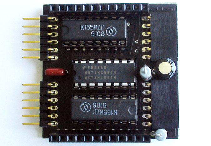
Another neat part is the controller boards for the tubes that utilize Russian made K155NA1 Driver chips.


The ones in this picture are newer but two out of my original set were much older and definitely looked as if they were from the 70's or 80's.  Unforgivably, they were both damaged, one permanently due to my negligence.  I shorted one out on a random piece of wire that I had left on my worktable and the other I had flexed the pins too much and two of them broke.  I was able to solder on new pins so it works but it was  a regrettable mistake.  Ohh well, ordered me up some replacements from the fine gentlemen over at Ardunix.

So wiring this project wasn't too big of a deal...in theory.  I had wired up parts of it on my breadboard before I had my Arduino mini but I did run into a few problems with some of the parts I was using.  First don't ever use radio shack perf boards unless you absolutely have to...They are junk!!  I ran into my first issues with soldering the perf boards was that it was very difficult to solder since the solder doesn't stick to the PCB.  But after screwing with my solder points I was able to make a custom sized board for my Arduino Mini that I thought looked really decent.  Unfortunately, due to not really understanding how to regulate the 9v power supply to 5v properly, I over volted my first Arduino board and blew it up.  Crap!  Ohh well, order me up another and away I go.  This time I used a radio shack perf board with copper contacts on them to help with my problem with the solder not sticking to the PCB.  Still, it wasnt the best.  The copper contacts were only on one side and only on the surface which didnt help much.  Plus the contacts weren't evenly spaced really well and caused me to burn up another board when my solder points merged and shorted out the board.    Crap!!!  I did have it going though.  The picture from my last post was using that board, but I tried adding the LED's after I took that picture.  Ohh well, third times a charm, and this time I bought a small 2"x2" perf board from Sparkfun with evenly spaced holes and contacts that passed though the board.  Nice!!!  Here's the finished product:


I cut out one of the mount holes to help make it fit better.  Also I went though a few RGB led's getting them soldered together and fitted behind the tubes.  The first set, I accidentally turned one of the led's around and causing three of them to "blow up".  The second set I tired something different to help my solder them easier but ended up pulling the pins off and was unable to solder them back.  Third times a charm and this time I used a technique used to make RGB LED Cubes.  Wrap in heat shrink tubing and here you go:


So I had mentioned that my first Arduino board smoked due to being over volted.  Well after that I ordered a "breadboard" power supply from sparkfun that will convert 9-12v to 3-5v.  I made a small modification of adding a heat sink to the voltage regulator and painting the super bright red led they had on board with some black model paint I had laying around.  Then I wired it up in parallel with a baral jack plug, which I actually didn't need, as there are pins to solder wires directly to the board but whatever. Then since I had wanted to keep the FTDI cable used to program the Arduino, I grabbed a short usb extension cable from my local pc shop and wired it up so I could use the FTDI cable to power the board.


Here's a short video showing the LED back light running with the clock as my finished product.  


And heres the code I used.  Thanks to the guy over at Tronixstuff for his clock code as well as the guy over at the applied platonics blog for his RGB LED code.  


/*
Nixie tube demonstration code - simple clock
http://tronixstuff.com - John Boxall. February 2011.
Baseon on a sketch originally created by Lionel Haims, July 25, 2008.
Released into the public domain.
*/

#include "Wire.h"
#include "Nixie.h"
#define DS1307_I2C_ADDRESS 0x68

// note the digital pins of the arduino that are connected to the nixie driver
#define dataPin 2 // data line or SER
#define clockPin 3 // clock pin or SCK
#define latchPin 4 // latch pin or RCK

// note the number of digits (nixie tubes) you have (buy more, you need more!)
#define numDigits 4

int narray[numDigits]; // holds the digits to display
int a=0;
// This assumes you're using a RadioShack #276-0028 RGB LED
// 2011-05-12: Note! The anode is the really long pin.
// You'll need to bend it to get it into Digital8.
//
// || || || ||
// || || || ||
// || || || ||
// G B || ||
// || R
// A
// D11 D10 D08 D09

int common_anode = 8;
int red_pin = 9;
int blue_pin = 10;
int green_pin = 11;

int red_min = 150;
int red_max = 255;

int blue_min = 185;
int blue_max = 255;

int green_min = 195;
int green_max = 255;

float h = 0.0;
float s = 1.0;
float v = 0.8;


// Create the Nixie object
// pass in the pin numbers in the correct order
Nixie nixie(dataPin, clockPin, latchPin);

// Convert normal decimal numbers to binary coded decimal
byte decToBcd(byte val)
{
return ( (val/10*16) + (val%10) );
}

// Convert binary coded decimal to normal decimal numbers
byte bcdToDec(byte val)
{
return ( (val/16*10) + (val%16) );
}

void setDateDs1307(byte second, // 0-59
byte minute, // 0-59
byte hour, // 1-23
byte dayOfWeek, // 1-7
byte dayOfMonth, // 1-28/29/30/31
byte month, // 1-12
byte year) // 0-99
{
Wire.beginTransmission(DS1307_I2C_ADDRESS);
Wire.send(0);
Wire.send(decToBcd(second)); // 0 to bit 7 starts the clock
Wire.send(decToBcd(minute));
Wire.send(decToBcd(hour));
Wire.send(decToBcd(dayOfWeek));
Wire.send(decToBcd(dayOfMonth));
Wire.send(decToBcd(month));
Wire.send(decToBcd(year));
Wire.send(0x10); // sends 0x10 (hex) 00010000 (binary) to control register - turns on square wave
Wire.endTransmission();
}

// Gets the date and time from the ds1307
void getDateDs1307(byte *second,
byte *minute,
byte *hour,
byte *dayOfWeek,
byte *dayOfMonth,
byte *month,
byte *year)
{
// Reset the register pointer
Wire.beginTransmission(DS1307_I2C_ADDRESS);
Wire.send(0);
Wire.endTransmission();
Wire.requestFrom(DS1307_I2C_ADDRESS, 7);
// A few of these need masks because certain bits are control bits
*second = bcdToDec(Wire.receive() & 0x7f);
*minute = bcdToDec(Wire.receive());
*hour = bcdToDec(Wire.receive() & 0x3f); // Need to change this if 12 hour am/pm
*dayOfWeek = bcdToDec(Wire.receive());
*dayOfMonth = bcdToDec(Wire.receive());
*month = bcdToDec(Wire.receive());
*year = bcdToDec(Wire.receive());
}

void setup()
{
byte second, minute, hour, dayOfWeek, dayOfMonth, month, year;
pinMode(latchPin, OUTPUT);
pinMode(clockPin, OUTPUT);
pinMode(dataPin, OUTPUT);
Wire.begin();
nixie.clear(numDigits); // clear display
pinMode(common_anode, OUTPUT);
digitalWrite(common_anode, HIGH);

pinMode(red_pin, OUTPUT);
digitalWrite(red_pin, HIGH);

pinMode(green_pin, OUTPUT);
digitalWrite(green_pin, HIGH);

pinMode(blue_pin, OUTPUT);
digitalWrite(blue_pin, HIGH);

Serial.begin(9600);

float h = 0.0;
float s = 1.0;
float v = 0.8;

// Change these values to what you want to set your clock to.
// You probably only want to set your clock once and then remove
// the setDateDs1307 call.

second = 30;
minute = 11;
hour = 17;
dayOfWeek = 3;
dayOfMonth = 11;
month = 5;
year = 11;

//setDateDs1307(second, minute, hour, dayOfWeek, dayOfMonth, month, year);
}

void nixNum(int z)
// displays integer 'z' on 4-digit nixe display
// keeps leading zero, as blank still flickers somewhat
{
narray[0]=int(z/1000); // thousands value
z=z-(narray[0]*1000);
narray[1]=int(z/100); // hundreds value
z=z-(narray[1]*100);
narray[2]=int(z/10); // tens value
narray[3]=z-(narray[2]*10); // ones value
nixie.writeArray( narray, numDigits);
}

void showTime()
{
int zzz=0;
byte second, minute, hour, dayOfWeek, dayOfMonth, month, year;
getDateDs1307(&second, &minute, &hour, &dayOfWeek, &dayOfMonth, &month, &year);
if (bcdToDec(hour)<1) { zzz=minute; } else if (bcdToDec(hour)>=1)
{
zzz=hour*100;
zzz=zzz+minute;
}
nixNum(zzz);
}
void hsv_to_rgb(float h, float s, float v, unsigned char *rc, unsigned char *gc, unsigned char *bc) {
int h_i = ((int)(h/60)) % 6;

float f = (h/60) - (int)(h/60);

float r,g,b;

float p = v * (1.0 - s);
float q = v * (1.0 - f*s);
float t = (1.0 - (1.0 - f)*s);

switch(h_i) {
case 0: r = v; g = t; b = p; break;
case 1: r = q; g = v; b = p; break;
case 2: r = p; g = v; b = t; break;
case 3: r = p; g = q; b = v; break;
case 4: r = t; g = p; b = v; break;
case 5: r = v; g = p; b = q; break;
}

*rc = red_max - (char)((red_max - red_min)*r);
*gc = green_max - (char)((green_max - green_min)*g);
*bc = blue_max - (char)((blue_max - blue_min)*b);
}

//void showDate()
//{
// int zzz=0;
// byte second, minute, hour, dayOfWeek, dayOfMonth, month, year;
// getDateDs1307(&second, &minute, &hour, &dayOfWeek, &dayOfMonth, &month, &year);
// zzz=(dayOfMonth*100)+month;
// nixNum(zzz);
//}

void loop()
{

unsigned char r,g,b;

h += 1;
if (h > 360.0) h -= 360.0;

hsv_to_rgb(h,s,v, &r,&g,&b);
analogWrite(red_pin, r);
analogWrite(green_pin, g);
analogWrite(blue_pin, b);
showTime(); // display the time
delay(100);


//a++;
//if (a==10)
//{
// showDate(); // display the date (day and month) for two seconds
// delay(2000);
// a=1;
//}
}
Even with all the problems I had getting this project finalized I really enjoyed working with this project and looking back at some of the stuff I was doing just a few months ago, I can definitely see a improvement in my abilitys.

I have actually already been asked how much it cost to get this going if i were to make another and I figure it would be about $300 for all the parts.  And now that I know what I'm doing, it probably wouldn't take me much more then a good day to build it.  Also, if you didn't notice, on the first part of these post, I linked a wish list on sparkfun with all the part that I used to make this product with a few more to expand it a little further (add buttons to change the time and turn on/off the back lights) if your interested in building your own. I also work for tips if you like one but don't have the soldering skills to do it yourself.  =D

Hey I've got a wedding to fund!  LOL!

That's it for now.  I think I'm going to take a break for a while while I save up for my wedding so keep it real peeps!

Tuesday, June 7, 2011

New Project: Nixie Clock part 1

And I'm back...

Its been a while since I updated my projects blog.  This is mostly because I got discouraged by my Hard Drive clock project.  I ran into a lot of problems and in the end, I took an extended break from it.  Eventually I may go back to it but for now I have something new and a little easier to work with, Nixie Tubes!!

If you remember from my last post, I was working on a clock project because there is not an easily accessible clock in the house.  Also you may remember that we were on a tight budget last time.  Well I got my excuse to get this project going, I turned 30.  Fitting right?  I thought so.  Also I needed something to break in my new Hakko Soldering Iron I got for my birthday.  Its awesome btw.  0-400 degrees in 10seconds.  Beats this shit out of the one I have at work.  I can go out for coffee before that one gets warm enough to melt solder.

So what are Nixie Tubes again?  A Nixie tube is an electronic device for displaying numerals or other information. The glass tube contains a wire-mesh anode and multiple cathodes. In most tubes, the cathodes are shaped like numerals. Applying power to one cathode surrounds it with an orange glow discharge. The tube is filled with a gas at low pressure, usually mostly neon. Nixies were used as numeric displays in early digital voltmeters, multimeters, frequency counters and many other types of technical equipment. They also appeared in costly digital time displays used in research and military establishments. They have been made obsolete by LED technology.

Except for in the Soviet Union, where they were mass produced into the '90s.

OK!  So lets get the parts list going cause a lots changed in the last few months.

Parts!

For this project, I ordered my Nixie Tubes from http://www.ogilumen.com.  Their kit was very easy to use and there were great instructions on their website for putting the parts together.  Here is what I ordered:

50 mA NIXIE TUBE POWER SUPPLY
OGI LUMEN provides this heavy lifter high voltage switch mode power supply pre-assembled.

It is currently offered in a 50mA output version, adjustable from 150 to 220 VDC, from a 9 to 16 VDC source. There is sufficient power produced by one 50 mA NIXIE TUBE POWER SUPPLY to drive twelve NIXIE DUO boards (twenty-four IN-12A nixie tubes). Our 12 VOLT AC/DC ADAPTER will easily drive this nixie tube supply.


NIXIE DUO and NIXIE DRIVER KITs
All parts provided for solder assembly of pictured extra thick epoxy boards. You get two phenolic sockets, two shiny NOS IN-12A nixie tubes, and all the other bits you'll need. The NIXIE DRIVER prepares a NIXIE DUO to receive serial input from an external microcontroller (Arduino), and power from a NIXIE TUBE POWER SUPPLY. You can further string these assemblies end-to-end for rows of humming digits.NIXIE DUO and NIXIE DRIVER KITs
I ordered 2 of the Nixie Duo and Nixie Driver Kits since I needed 4 digits. 

The next set is from http://www.sparkfun.com.  I ended up needing a lot of little parts so for simplicity, i created a wish list which you can access here:  Parts for Nixie Tube Clock  I'll try to explain what the "odd" parts are for quickly:

Momentary Push Button Switch: Controls to change time as well as "theme"

Triple Output LED RGB: Back light for the Nixie Tubes

FTDI Cable 5V: Programming cable for my Arduino mini Pro

Breadboard Power Supply 5V/3.3V: Ran into problems my first build getting steady 5v power to my Arduino. I ended up burning out the boot loader on my first Arduino as well as two voltage regulators, so I got this for simplicity. There are heat sinks in the list for the voltage regulator as well.

DC Barrel Jack Adapter: Got this to easily connect the Breadboard Power Supply in parallel to my Nixie Tube Power Supply.

Screw Terminals 5mm Pitch (2-Pin) & (3-Pin): Got these to easily connect my lines to the Nixie Tube Power Supply without jacking up the solder points.  I added these to the list in retrospect since I ended up soldering and desoldering my power lines a few times and damaging the board a little.

I also picked up a small 9"x20" Shadow Box from Michael's to house the project.  I had to modify it a little for my purposes.  I removed the glass panel because the box ended up being not deep enough and I replaced the foam board backing with a 3/8" thick piece of basswood from JoAnn Fabrics as well as some black fabric from JoAnn as well.  I used two layers of the fabric hide the cables I ran underneath.  Finally, I went to radio shack and picked up a sheet of perforated board for any small custom sized boards i need as well as a pack of 100ohm resistors for the led back lights.

The Build
So here is the working project.  I'll post how I built the clock later.  For now, Enjoy.

Tuesday, March 1, 2011

Concepts for upcoming projects

Ok so I've come up with a few new ideas for projects I'd like to play with.

The Bluetooth Joystick Project
Concept and scope of use:
To create a handheld, usb powered game pad using the joystick kit from sparkfun.com with a Bluetooth modem in order to connect to my Droid Incredible Smartphone to play The Legend of Zelda on my phone's SNES emulator.  
Parts:
Both of the following items have already been purchased from Sparkfun Electronics.

Joystick Shield Kit
sku: DEV-09760
Description: The Joystick Shield kit contains all the parts you need to enable your Arduino with a joystick! The shield sits on top of your Arduino and turns it into a simple controller. Five momentary push buttons (4+ joystick select button) and a two-axis thumb joystick gives your Arduino functionality on the level of old Nintendo controllers


Bluetooth Modem - BlueSMiRF Silver

sku: WRL-10269
Description: The BlueSMiRF Silver is the latest Bluetoothwireless serial cable replacement from SparkFun Electronics! This version of the popular BlueSMiRF uses the RN-42 module which has a bit less range than the RN-41 module used in the BlueSMiRF Gold. These modems work as a serial (RX/TX) pipe. Any serial stream from 9600 to 115200bps can be passed seamlessly from your computer to your target.


Notes:
The basic problem is that the SNES emulator works great but my big thumbs cover most of the touchscreen and its difficult to use the on screen controls.  The idea for this project being, if can use my Ardunio to take the input from my joystick and buttons and then output those commands over bluetooth in a way that my SNES emulator will use them.  We will see how it all turns out when i get my parts in the next week.

Bonus points:  If the concept works, repackage it and see if its viable to use the phones battery over usb to power the joystick.

The Speedometer Project
Concept and scope of use:
To create a Digital Speedometer with a Odometer and Compass functions.
Parts:

Serial Miniature LCD Module 1.44"

sku: LCD-10090
Description: The uLCD-144(GFX) is a compact and cost effective  display module using the latest state of the art LCD (TFT) technology with an embedded GOLDELOX-GFX2 graphics processor that delivers ‘stand-alone’ functionality to any project. Powerful graphics, text, image, animation and countless more features are built inside the GOLDELOX-GFX2 chip.


Im actually buying this as individual parts instead of a kit.  

GPS Shield

sku: GPS-10102
Description: Adding GPS to your Arduino has never been easier. The multiple GPS receivers attach easily to the shield, and with the example sketch, you will be able to locate your exact position within a few meters.

20 Channel EM-406A SiRF III Receiver with Antenna

sku: GPS-00465
Description: The EM-406A GPS module from USGlobalSat based on the spectacular SiRF StarIII chipset. This complete module is built upon the same technology as the ET-301, but includes on-board voltage regulation, LED status indicator, battery backed RAM, and a built-in patch antenna! 6-pin interface cable included.

Real Time Clock Module

sku: BOB-00099
Description: This a custom designed module for the DS1307 Real Time Clock. The module comes fully assembled and pre-programmed with the current time.


Notes:
I really liked digital speedometers.  For example, like the ones currently in the Honda Civics.  Personally, I really don't understand why car manufactures don't utilize them more.  The old analog gages are completely outdated.  Seriously, its 2011, time to come into the future.  The Idea of this project is create a digital speedometer with extra features to use in my car, without input from the cars sensors.  This way i can use the project in a number of different situations.  I'll use the GPS receiver to get location data and time from the navsats.  Then take the data to show direction, speed, location(optional), distance traveled, date and time.  Then output that data to the LCD screen. You might be wondering why I even included the RTC chip since time-of-day and date can be received from the GPS data. The DS1307 RTC chip also has 56 bytes of non-volatile RAM. I'm using these registers for storing the trip meter and odometer values so they can be restored between power cycles.

Bonus points:  If the concept works, repackage it in a waterproof box and see if its viable to use alternative energy to power the device, be it wind or solar power.

The Nixie Clock Project
Concept and scope of use:
To create a clock using Nixie Tubes to display the time while also using wireless to keep the clock updated to the correct time. 
Parts:
Description: 50 mA NIXIE TUBE POWER SUPPLY 

OGI LUMEN provides this heavy lifter high voltage switch mode power supply pre-assembled. 

It is currently offered in a 50mA output version, adjustable from 150 to 220 VDC, from a 9 to 16 VDC source. There is sufficient power produced by one 50 mA NIXIE TUBE POWER SUPPLY to drive twelve NIXIE DUO boards (twenty-four IN-12A nixie tubes). Our 12 VOLT AC/DC ADAPTER will easily drive this nixie tube supply. 


Description: NIXIE DUO and NIXIE DRIVER KITs

Whoa! The NIXIE DUO and NIXIE DRIVER together for the first time!

nixie tubes, and all the other bits you'll need. The NIXIE DRIVER prepares a NIXIE DUO to receive serial input from an external microcontroller (Arduino), and power from a NIXIE TUBE POWER SUPPLY. You can further string these assemblies end-to-end for rows of humming digits. 


Description: NEON LAMP

Neon glows orange-red within these lens topped beauties. We've got hundreds more for when nothing but neon is the answer. 


WiShield 2.0


This is the shield you need to get Wi-Fi connectivity to your Arduino-based project! This shield provides 802.11b connectivity and is a direct drop-on plug-and-play solution to your Arduino Diecimila/Duemilanove/Uno.
The second revision of this board has all the components in surface mount form.  The new and exciting feature of the second revision of this board is the addition of a 16Mbit serial flash for storing web pages and other data!  This additional storage space can be used for storing more complex and feature rich webpages, as well as sensor type data to be downloaded at a future time


Note:
What is a Nixie Tube?  A nixie tube is an electronic device for displaying numerals or other information. The glass tube contains a wire-mesh anode and multiple cathodes. In most tubes, the cathodes are shaped like numerals. Applying power to one cathode surrounds it with an orange glow discharge. The tube is filled with a gas at low pressure, usually mostly neon.  Nixies were used as numeric displays in early digital voltmeters, multimeters, frequency counters and many other types of technical equipment. They also appeared in costly digital time displays used in research and military establishments.  They have been made obsolete by LED technology.  In this project, I want to try to make a clock with a coldwar feel to it.  That and the added feature of always being up to date even during daylight savings thanks to the National Institute of Standards and Technology's time feed.

Bonus Points:  Make a nice wood cabinet for it so I can show it off in my living room.
Secondary Bonus Points: Backlight the tubes with leds similar to the following: